RO UV Water Purifier Installation Diagram (+ Guide)
Written by: Gene Fitzgerald // Last Updated: Aug 15, 2023
This page may contain affiliate links. If you buy a product or service through such a link we earn a commission at no extra cost to you. Learn more.
RO UV water purifiers provide you with top-of-the-line water filtration both in terms of contaminant reduction and disinfection. These systems combine a traditional reverse osmosis purification system with a UV filter stage to ensure almost any water contamination is completely eradicated.
While RO UV systems are about as good as it gets when it comes to home water filtration, they aren’t the easiest things in the world to install yourself. Of course, you can always pay a plumber to complete the installation for you, but if you’re comfortable with basic DIY you can save on costs and hook up the unit yourself.
Need help? Check our RO UV water purifier installation diagram!
Contents
show
RO UV Water Purifier Installation Diagram
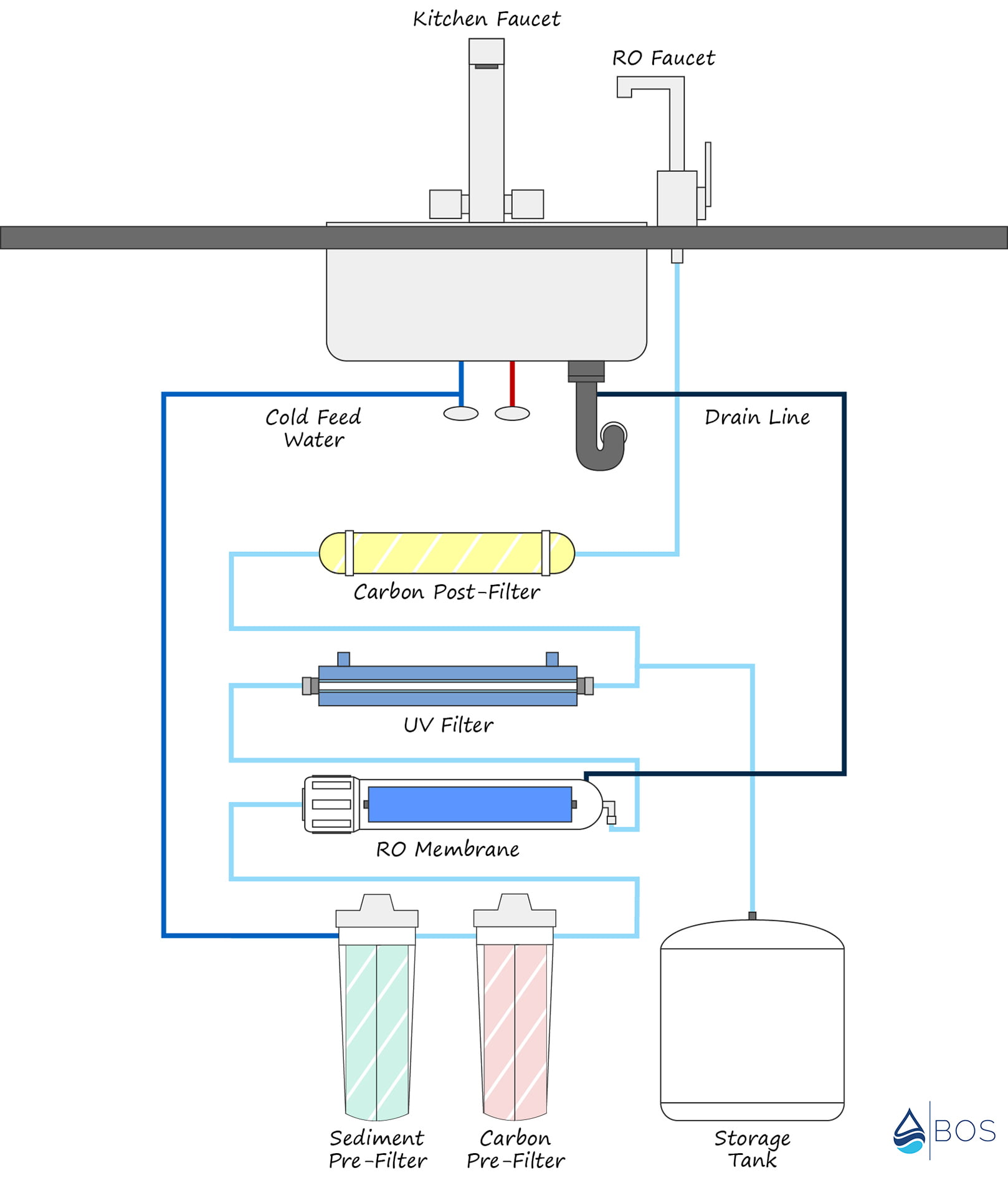
Reverse Osmosis + UV System Installation Components
RO UV systems are sophisticated pieces of technology and feature multiple filtration stages in addition to valves, fittings, housings, and a storage tank. Let’s examine these components in detail.
RO System Module
The RO system module is the body of the RO system without the membrane, filters, and housings attached. It may or may not come with a pump for improving the system’s efficiency.
Inlet Valve
The inlet valve – sometimes called the feed water valve – is a valve connecting the RO system to your water supply. Unfiltered cold water flows through this valve before it reaches the first pre-filter stage.
Pre-Filters
Typical RO systems feature two pre-filters: a carbon pre-filter mainly to remove chlorine/chloramine and a sediment pre-filter to remove large floating particles. These are included as pre-filters meaning before the water reaches the reverse osmosis membrane as both of these contaminants could damage a membrane if they are allowed to touch it.
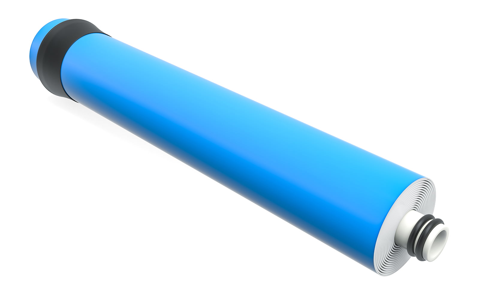
RO Membrane
The semipermeable membrane is the heart of any RO system. It removes a wide variety of impurities from your water. The membrane itself is ultra-fine, which allows it to remove impurities down to just .0001 microns.
UV Filter Stage
The UV filter stage is different from the other stages in that it doesn’t filter anything out of the water. Instead, it uses powerful UV rays to kill any microbial contamination that remains in the water.
UV Lamp
The UV lamp is the heart of the UV filter stage. These lamps typically use a bulb operating at 254 nanometers (nm), which is the optimal level for disrupting microbial DNA.
The lamp is mounted in the middle of the UV filter, so the water flowing around it is equally exposed to the UV light.
Quartz Sleeve
The UV lamp is housed inside a clear quartz sleeve. Quartz is used instead of regular glass because it has superior UV light transmission.
The only downside of quartz is that it tends to fog up over time, so it must be cleaned regularly and eventually replaced.
Storage Tank
RO systems utilize a storage tank to keep filtered RO water ready whenever you need it. RO systems filter water at a fairly slow rate, so without a tank, you would be waiting forever every time you opened the faucet to fill up a glass.
A system will filter water until the tank is full, at which point it will shut itself off automatically.
Post-Filter
RO systems utilize one or more post-filters after the water has passed through the membrane. The purpose of this filtration stage is to “polish” the water and improve its taste.
Automatic Shut-Off Valve
The automatic shut of valve prevents the system from continuously filtering water once the storage tank is filled. When the tank fills up, the valve is activated and stops any more water from flowing through the membrane.
When you pour water out of the faucet, the pressure in the storage tank drops, which turns off the valve and begins the filtration process.
Check Valve
The check valve is attached to the outlet of the RO membrane and is used to prevent any water from flowing backward into said membrane. Water flowing backward through the membrane can damage or even rupture it, so this valve is vital in keeping the RO UV system working.
Flow Restrictor
The flow restrictor limits the flow of wastewater out of the system. This keeps the pressure inside the RO membrane high enough for it to work properly. Without a flow restrictor, water would flow unimpeded down the drain line, wasting tons of water.
RO Faucet
The RO faucet is simply the name for the faucet that dispenses the filtered RO water when needed. This faucet is separate from your main kitchen faucet, so you won’t be wasting filtered water on cleaning and washing dishes and the like.
Drain Line and Saddle
The drain line, as you might expect, is the line that disposes of the wastewater generated by the RO membrane. It runs from the membrane outlet to your sink’s plumbing. The saddle is the valve that connects the RO system to the plumbing – allowing wastewater to drain away.
Quick-Connect Fittings
Most RO systems feature quick-connect fittings. These push-lock fittings allow you to attach tubing by simply pushing them in place. Quick connect fittings are much easier to work with than other types and will attach/detach in seconds.
Tubing
Typical RO systems use ¼” food-grade polyethylene tubing. This tubing is designed to work with quick-connect fittings and can be cut down to size with tube cutters or a utility knife.
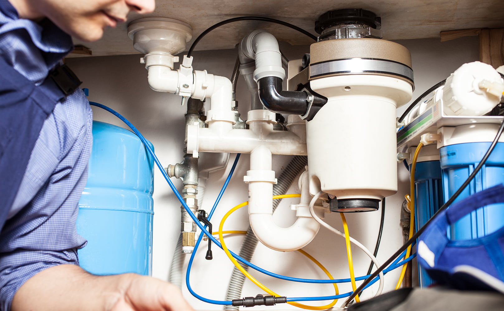
How to Install an RO UV Water Purifier
Installing an RO UV water purifier is not the easiest DIY task out there. However, with a few basic tools and the detailed instructions outlined here, you should be able to replicate the process under your sink.
Preparation: Tools You’ll Need
- Utility Knife or tube cutter
- Adjustable wrench
- Drill with ¼” and ½” bits
- Plumber’s tape
- Screwdriver
- Center punch
Installation Steps
The Faucet
The first step to the RO UV installation will be installing the filtered water faucet.
If you’re lucky, your sink will have an existing hole for a sprayer or soap dispenser that can be repurposed. If that’s the case, all you’ll need to do is remove any existing sprayer/soap dispenser and position the faucet inside the hole.
If you don’t have an extra hole, then you’ll need to drill one through either the sink or the adjacent countertop. The drill bit required will depend on whether you’re drilling through metal or porcelain or whatever sink/countertop material you have, but the process will be similar regardless.
First, mark the hole location using your center punch. Then use a ¼” inch bit to start drilling a pilot hole through the material.
When your pilot hole has punched through the material switch the ¼” inch pilot hole bit for a ½” bit. Then enlarge the hole to ½” and clean up any rough edges.
Lastly, feed the faucet step through the hole and secure it by tightening the washer and hex nut from below. Tighten it with a wrench to make sure it won’t move.
Feed Valve
Next, we’ll install the feed valve that supplies raw water to the system.
Before you begin, you’ll need to turn off the cold water supply to your sink. Then turn on the cold faucet to remove any pressure remaining in the water line.
Disconnect the existing tubing from the cold water valve, and install the new 2-way feed valve.
At this point, you can reconnect the old cold water tubing to the new feed valve. You now have two lines running out of your cold water supply: one to the old faucet, and one to your RO system.
When making threaded connections here (and anywhere else in the system) adding a little plumbers tape will help keep things watertight.
Drain Saddle
The drain saddle connects the drain line from your RO system to the drain under the sink. Other than drilling a hole for the faucet, installing the drain saddle may be the trickiest part of the installation.
You’ll want to position the drain saddle at least 6 inches above the P-trap and away from any dishwasher or garbage disposal lines.
First, drill a ¼” hole through one side of the drain line. Then, align the drain clamps around the hole and carefully tighten them so that the foam gasket is positioned around the hole.
Tank
Position the storage tank in the location you plan to keep it after the installation. Storage tanks should be positioned within 10 feet of the RO unit to avoid losing water pressure.
If there isn’t enough space underneath your sink, you can always store it in an adjacent cabinet, and it can even be placed on its side to accommodate tighter spots.
Mount System Module
Most RO system modules come with optional mounting holes that allow you to mount the entire unit to the back or side of your under-sink cabinet. This isn’t strictly necessary, but it will save space and make performing maintenance on the system easier most of the time.
When mounting the module, it’s important to make sure you have enough clearance underneath them to detach the filter and membrane housings.
Connect Initial Tubing
At this point, you can begin connecting some of the tubing to the various fittings. The exact process will depend on your specific setup, so follow the manufacturer’s instructions if in doubt.
The supply line running from the feed valve should be connected with the input on the RO module.
The drain line running from the flow restrictor should be connected to the drain saddle.
Connect the line running from the RO faucet to the post filter outlet (or the UV filter outlet) depending on which is the final filtration stage.
Further Reading:
Filter Elements
Now that you have most of the system assembled, it’s time to insert the various filters into their housings/vessels.
Pre-Filters
Remove the pre-filters from their packaging, and slide them into their respective housings. Then carefully screw them back into place ensuring the O-rings are in position.
RO Membrane
The RO membrane is delicate and should be handled carefully to prevent accidental damage. Use gloves or handle it through its plastic packaging to avoid fouling.
Insert the RO membrane into its housing with the O-ring end first. Then put the cap on and make sure it’s secured properly.
UV Light
Just like the RO membrane, the UV bulb is sensitive, so be sure not to touch it directly during installation. Depending on your specific model, the steps to set it up might vary, but this should give you as basic idea:
- Unscrew the cap counterclockwise from the UV bulb housing.
- Put the O-Ring around the open end of the quartz sleeve.
- Insert the open end of the quartz sleeve into the end cap. The O-Ring should rest against the cap.
- Insert the closed end of the quartz sleeve into the open end of the UV bulb housing with the cap over the end.
- Screw the cap clockwise onto the UV housing. Use a pair of vise grips or an adjustable wrench to tighten it shut, being careful not to over-tighten. Make sure not to use Teflon tape on the UV cap connection.
- Connect the electric socket on the power cord to the UV bulb.
- Carefully insert the UV bulb through the opening in the cap into the quartz sleeve.
- Push the plastic cover attached to the power cord in place over the cap.
- Finally, connect the power cord from the UV filter to a wall outlet.
Post-Filter
Installing the post-filter in the module follows the same process as installing the pre-filters and membrane.
Remove the post-filter from its packaging and slide it into its housing on the module. Screw the housing in place until its tight, making sure the O-ring stays in place.
Connect Remaining Tubing
At this point, the process is almost complete. All that’s left to do is hook up any remaining connections which you didn’t get to earlier.
Be sure to follow the manufacturer’s directions closely while making connections. Also, short tubing connections (especially from the tank to the RO system) will make the system more efficient, so try not to run excessively long connections whenever possible.
If you have any questions about our RO UV water purifier connection diagram please don’t hesitate to leave a comment below!
About the Author Gene Fitzgerald
![]()
![]()
![]()
![]()
![]()
![]()
![]()

Information provided on BOS is for educational purposes only. The products and services we review may not be right for your individual circumstances.
We adhere to strict editorial guidelines. Rest assured, the opinions expressed have not been provided, reviewed, or otherwise endorsed by our partners – they are unbiased, independent, and the author’s alone. We fact-check all content for accuracy. It is accurate as of the date posted and to the best of our knowledge.