RO UV Water Purifier Flow Diagram | Everything at a Glance
Written by: Gene Fitzgerald // Last Updated: Aug 15, 2023
This page may contain affiliate links. If you buy a product or service through such a link we earn a commission at no extra cost to you. Learn more.
RO UV water purifiers are home filtration units that combine the wide spectrum contaminant filtration of reverse osmosis systems with the superior microbial eradication of UV filters.
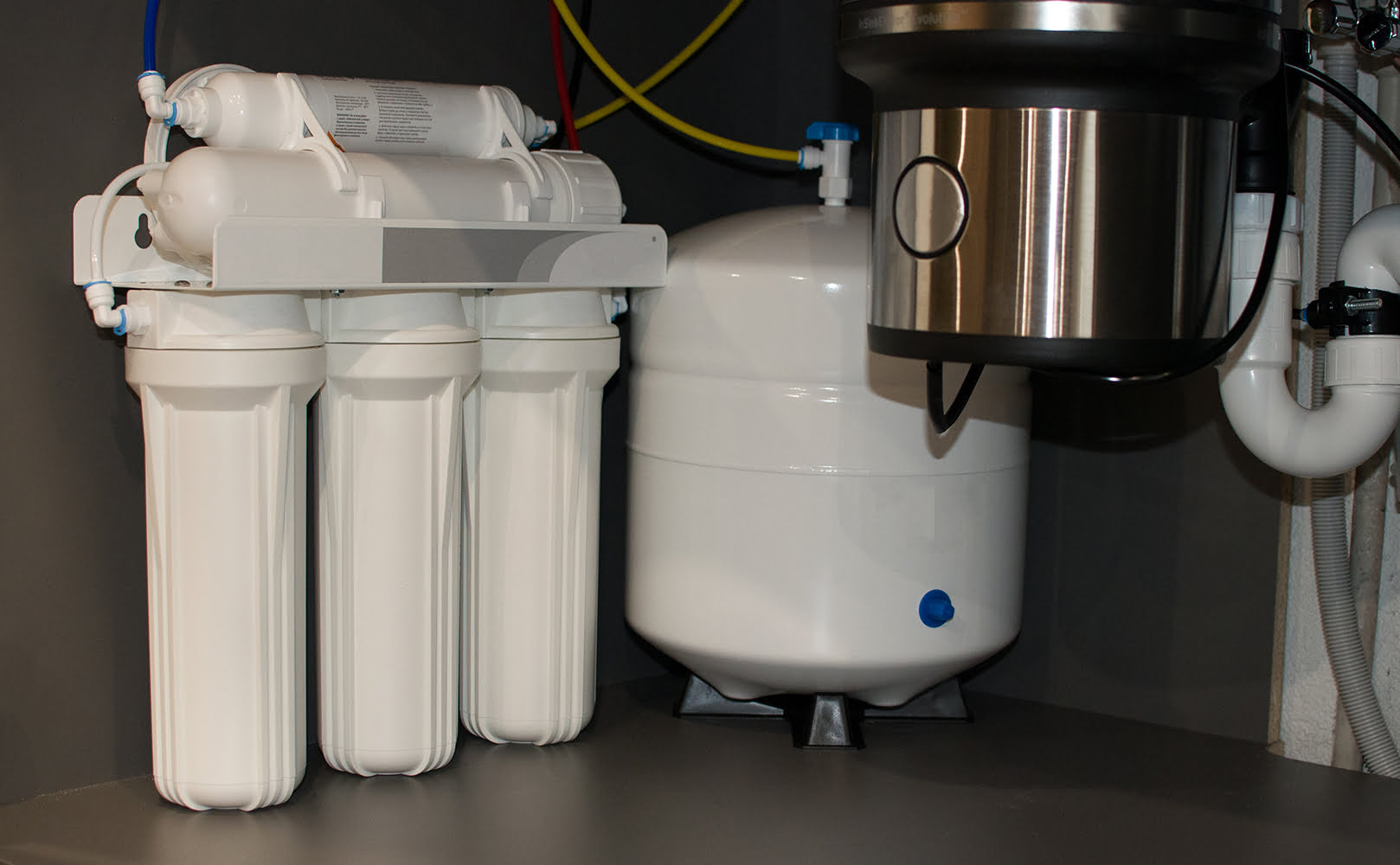
These filters are typically installed as point-of-use systems – meaning they’re mounted underneath your kitchen sink.
So, what does the RO UV purification process look like in detail?
The following diagram outlines the flow of water through the entire system – from the unfiltered feed water supply to the clean filtered water flowing out of the reverse osmosis faucet.
Contents
show
Key Takeaways
- RO UV water purifiers are slightly more complex than typical RO systems due to the additional UV filter stage. The UV filter is typically included after the RO membrane stage.
- A typical RO UV water purifier uses the following components: Feed water valve, pre-filters, RO reverse osmosis membrane, UV light bulb, water storage tank, post-filter, ASO and check valve, flow restrictor, drain line, RO faucet.
RO UV Water Purifier Flow Diagram
Find our reverse osmosis + UV water purifier flow diagram below:
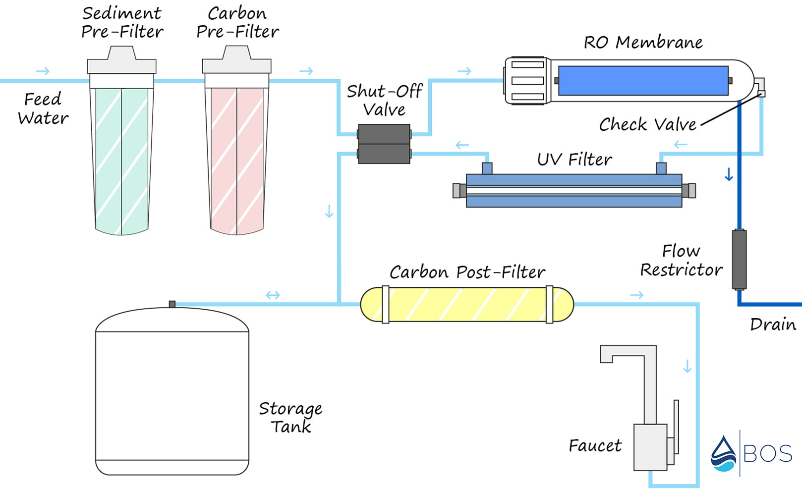
What’s Inside an RO UV Water Purifier and How Do the Different Components Work?
Typical reverse osmosis systems feature several pre-filters to remove contaminants before the feed water reaches the RO membrane. Then after the feed water passes through the membrane it’s filtered once more by a carbon post-filter to ‘polish’ the taste.
RO UV filters add one additional stage to this process – a UV light to eradicate any microbial contamination that makes it past the membrane.
Feed Water Valve
The feed water valve connects the RO system to your sink’s cold-water supply. Unfiltered feed water then flows through the valve before it reaches the first pre-filter stage.
Sediment Pre-Filter
A sediment pre-filter is used to remove large particulate matter that could clog up the RO membrane. Think silt, sand, dirt, and other sediments.
Carbon Pre-Filter
The carbon pre-filter is used primarily to remove chlorine/chloramine + chemicals from the feed water. Chlorine can damage the RO membrane, so it must be removed before the water reaches the membrane stage.
Further Reading:
Reverse Osmosis Membrane
The reverse osmosis membrane is the heart of the RO system. It removes a wide range of contaminant particles including heavy metals, VOCs, pesticides/herbicides, nitrates/nitrites, minerals and salts, and most microbes.
Feed water is forced through the semipermeable membrane under pressure – which captures contaminants down to .0001 microns!
UV Light
RO UV systems typically include the UV light right after the RO membrane. This stage uses a long UV bulb mounted inside a quartz glass sleeve to eradicate over 99.9% of harmful germs.
Because UV filters don’t work as effectively when particles are present, the UV stage is added on after the feed water has gone through pre-filtration as well as the RO membrane.
Another point to note is that UV filters require a power source for the bulb, so they won’t operate if the power is out.
Water Storage Tank
Because the RO filtration process is fairly slow, a storage tank is needed to keep filtered water on tap at all times. The tank will automatically fill itself up once the system is turned on, and once full it will automatically shut off the filtration process.
Post-Filter
A post-filter (typically another type of carbon filter) is used to remove any remaining contaminants and ‘polish’ the water’s taste. The post-filter stage is located after the storage tank.
ASO Valve
The ASO (Automatic Shut Off) valve is used to prevent the system from continuously filtering water. When the storage tank is filled, water pressure from the tank activates this valve – which stops additional feed water from flowing into the RO membrane.
Check Valve
The check valve is one of the fittings attached to one of the outlets from the reverse osmosis membrane (the other being the drain line). Its purpose is to ensure no water can flow backward from the storage tank toward the membrane.
Water flowing backward through the RO membrane can damage and even rupture it, so this valve is critical in keeping the system operating.
Flow Restrictor
The flow restrictor restricts the flow of wastewater down the drain line. The entire RO system requires a certain water pressure to operate properly, and wastewater flowing down the drain line must be restricted to maintain this pressure.
Drain Line
This one is pretty self-explanatory – it’s the drain line running from the RO membrane to your sink’s drain pipe. The outlet end of the drain line must be attached to your drain pipe with a drain saddle – which requires drilling a hole.
Reverse Osmosis Faucet
Reverse osmosis systems use a separate faucet from your sink’s primary faucet. These are often mounted inside the sink’s sprayer/soap dispenser hole.
If you have any questions about our RO UV water purifier flow diagram please don’t hesitate to leave a comment below!
About the Author Gene Fitzgerald
![]()
![]()
![]()
![]()
![]()
![]()
![]()

Information provided on BOS is for educational purposes only. The products and services we review may not be right for your individual circumstances.
We adhere to strict editorial guidelines. Rest assured, the opinions expressed have not been provided, reviewed, or otherwise endorsed by our partners – they are unbiased, independent, and the author’s alone. Our licensed experts fact-check all content for accuracy. It is accurate as of the date posted and to the best of our knowledge.